

How Do Solar Branch Connectors Enable Scalable PV System Design?
2025-12-16
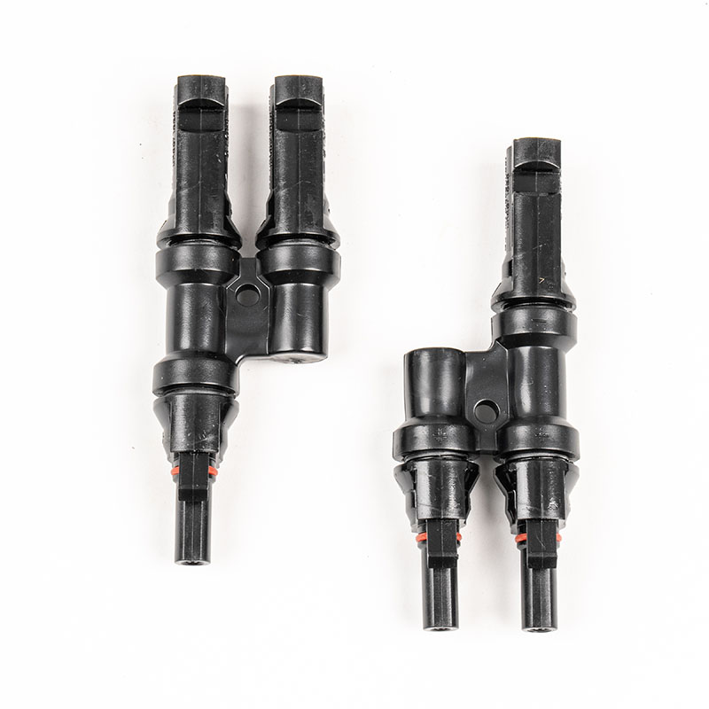
Solar branch connectors are critical interconnection components used in photovoltaic (PV) systems to combine multiple module strings into a single output while maintaining electrical integrity, safety, and installation efficiency.
How Are Solar Branch Connectors Used Within PV Electrical Architecture?
In a typical PV system, solar modules are wired in series to achieve the required voltage and in parallel to increase current capacity. Solar branch connectors, commonly configured as 2-to-1, 3-to-1, or multi-branch interfaces, are designed to merge parallel strings without the need for external junction boxes. This integration reduces wiring complexity and minimizes potential points of failure.
From an electrical architecture perspective, a solar branch connector functions as a controlled convergence point. Each input branch maintains independent polarity alignment, while the internal conductive paths are engineered to balance current flow and reduce resistive losses. Contact resistance is a key design consideration, as even minor increases can lead to localized heating under continuous load conditions.
Material selection plays a decisive role. High-conductivity copper alloys are typically used for contacts, while housings are manufactured from UV-resistant, flame-retardant thermoplastics. These materials ensure stable performance under prolonged exposure to outdoor environments, including temperature cycling, humidity, and solar radiation.
The connector’s locking mechanism is equally important. A secure mechanical lock prevents accidental disconnection caused by vibration, wind load, or thermal expansion. At the same time, standardized release tools allow maintenance personnel to disconnect branches without damaging the housing or contacts, preserving system serviceability over its operational lifespan.
How Do Electrical Parameters Define Solar Branch Connector Selection?
Selecting an appropriate solar branch connector requires careful evaluation of electrical and mechanical parameters to ensure compatibility with the overall PV system design. Mismatched specifications can result in derating, increased failure risk, or non-compliance with regional electrical codes.
The following table summarizes key technical parameters commonly specified for professional-grade solar branch connectors:
| Parameter | Typical Specification Range |
|---|---|
| Rated Current | 30 A to 60 A |
| Rated Voltage | 1000 V DC to 1500 V DC |
| Contact Resistance | ≤ 0.5 mΩ |
| Insulation Material | PPO or PA, UV-resistant |
| Conductor Cross Section | 4 mm² to 10 mm² |
| Operating Temperature | -40°C to +85°C |
| Protection Rating | IP67 / IP68 (mated) |
| Compliance Standards | IEC 62852, UL 6703 |
Rated current and voltage must always exceed the system’s maximum operating conditions, including potential overcurrent scenarios caused by uneven string loading. Protection ratings such as IP67 or IP68 indicate resistance to dust ingress and temporary or continuous immersion, which is particularly relevant for ground-mounted or rooftop systems exposed to rainfall and cleaning procedures.
Compliance with international standards is not merely a formality. Certification ensures that the connector has undergone thermal cycling, damp heat, mechanical stress, and electrical endurance testing. These evaluations simulate real-world operating conditions and provide assurance of long-term reliability.
How Does Installation Practice Affect Long-Term Connector Performance?
Proper installation is a decisive factor in the operational stability of solar branch connectors. Even connectors manufactured to high specifications can underperform if installation protocols are not followed precisely.
Crimping quality is one of the most influential variables. The conductor must be stripped to the correct length, and the crimping tool must match the terminal geometry specified by the connector manufacturer. Inconsistent crimp pressure can lead to increased contact resistance, which may not be immediately apparent during commissioning but can degrade performance over time.
Cable management also influences connector longevity. Excessive tensile load on branch connections should be avoided, as constant mechanical stress can weaken contact interfaces. Adequate slack and proper routing reduce strain and allow for thermal expansion without compromising the electrical joint.
Environmental placement is another consideration. While solar branch connectors are designed for outdoor use, avoiding direct contact with sharp edges, standing water, or areas of persistent shading can mitigate localized thermal and moisture-related stresses. When connectors are positioned beneath modules, airflow and heat dissipation should be taken into account to prevent unnecessary temperature rise.
Routine inspection during scheduled maintenance cycles helps identify early signs of wear, discoloration, or seal degradation. Addressing minor issues at this stage prevents escalation into system-level faults that could lead to downtime or safety hazards.
How Do Solar Branch Connectors Adapt to Evolving PV System Configurations?
PV system design continues to evolve in response to higher module wattage, increased system voltages, and more complex array layouts. Solar branch connectors are adapting accordingly, with designs that accommodate higher current densities and broader conductor compatibility.
As 1500 V DC systems become more prevalent, connectors must maintain dielectric strength while controlling thermal behavior under higher electrical stress. Enhanced insulation materials and optimized internal geometries are being implemented to meet these demands without increasing connector size.
Another adaptation involves modular scalability. Branch connectors that support flexible string combinations enable system designers to adjust array configurations without extensive rewiring. This adaptability is particularly valuable in commercial and utility-scale projects where phased expansion or partial repowering is anticipated.
Interoperability is also gaining attention. Consistent dimensional tolerances and standardized interfaces reduce the risk of mismatch when components from different production batches are deployed. This consistency supports inventory management and simplifies on-site assembly, especially for large installations with tight project timelines.
Common Questions About Solar Branch Connectors
Q: How is current balance maintained when multiple strings are combined through a solar branch connector?
A: Current balance is achieved through low-resistance conductive paths and uniform contact geometry, ensuring that each parallel string contributes proportionally without creating localized heating or electrical imbalance.
Q: Can solar branch connectors be reused after system modification or expansion?
A: Reuse is possible if the connector housing, seals, and contacts remain undamaged and within specification; however, inspection and verification against original performance criteria are essential before redeployment.
Solar branch connectors play a foundational role in the reliability and scalability of photovoltaic systems by providing secure, compliant, and efficient string interconnection. When specified according to electrical parameters, installed using correct procedures, and integrated into a forward-compatible system design, these components contribute to stable energy delivery across diverse deployment environments. Dsola supplies solar branch connectors engineered to meet stringent international standards and practical installation demands. For project consultation, technical documentation, or product selection support, contact us to discuss specific application requirements and system objectives.