

How Are High Voltage Circuit Breakers Used in Power Substations?
2026-09-02
In substation design, the placement and rating of a High Voltage Circuit Breaker is never arbitrary. Every breaker serves a specific zone of protection, a defined fault current level, and a coordinated time current characteristic. This article follows the design sequence of a typical 110 kV substation expansion, explaining the engineering decisions at each step.
1. How Do You Determine the Protection Zones That a Breaker Must Cover?
A substation is divided into protection zones: the incoming transmission line, the busbar, the transformer, and the outgoing feeders. Each zone requires a High Voltage Circuit Breaker that can isolate faults within that zone without affecting other zones. This is the principle of selectivity. When designing a new substation, the first step is to draw the one line diagram and assign a breaker to each zone boundary. For a double busbar configuration, each feeder typically has two breakers, allowing for maintenance without outage. In our factory, we produce High Voltage Circuit Breaker units that are tested for zone selective interlocking. This means the breaker can communicate with upstream and downstream protection relays to determine the fault location and trip accordingly. Our Lugao has supplied breakers for substations where the fault clearing time was reduced from 120 ms to 60 ms simply by implementing zone selective coordination.
Design principle for procurement: Verify that the breaker's protection relay interface supports IEC 61850 GOOSE messaging. This protocol enables fast peer to peer communication, which is essential for zone selective interlocking. Without this capability, the substation cannot achieve full selectivity.
2. How Is the Interrupting Capacity Matched to the Fault Current Level?
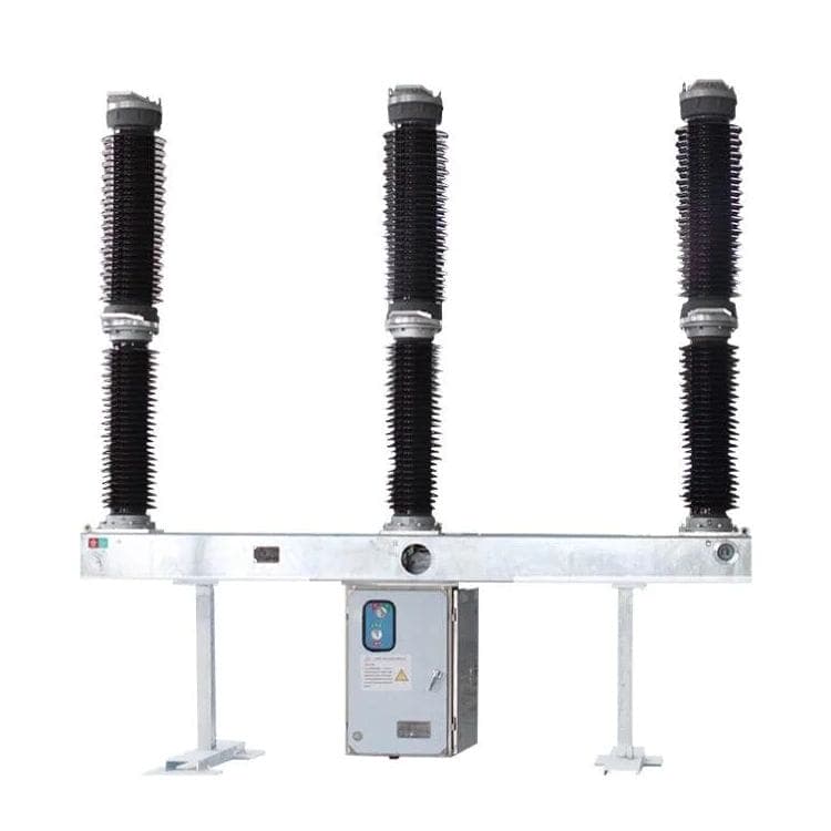
The interrupting capacity of a High Voltage Circuit Breaker must exceed the maximum symmetrical short circuit current at its installation point. This is determined by a fault current study that considers the source impedance, transformer impedance, and the network configuration. For a 110 kV substation fed by a 200 MVA transformer with 12 percent impedance, the fault current at the secondary side can reach 25 kA. The breaker must be rated for at least 31.5 kA to provide a safety margin. The table below shows the typical interrupting capacity requirements for different voltage levels.
| Nominal voltage (kV) | Typical fault current (kA) | Minimum interrupting capacity (kA) | Recommended breaker type |
| 33 | 12 – 16 | 20 | Vacuum or SF6 |
| 66 | 16 – 20 | 25 | SF6 or vacuum |
| 110 | 20 – 25 | 31.5 | SF6 (tank type) |
| 220 | 25 – 31.5 | 40 | SF6 (live tank) |
| 400 | 31.5 – 40 | 50 | SF6 (dead tank) |
In our factory, we manufacture High Voltage Circuit Breaker units with interrupting capacities from 20 kA to 63 kA, covering the full range of substation applications. We provide a short circuit calculation service to help engineers verify that the selected breaker is correctly sized. Our Lugao Power Co.,Ltd. recently supplied breakers for a 110 kV substation where the fault current was calculated at 22.7 kA. We recommended a 31.5 kA breaker, which allowed for future network expansion without replacing the equipment.
3. How Do You Coordinate the Tripping Time with Downstream Protection Devices?
Coordination is the process of ensuring that the breaker closest to the fault trips first, while upstream breakers remain closed. This is achieved by grading the time current curves. The High Voltage Circuit Breaker has a specific operating time: the time from receiving the trip signal to the moment the contacts part. This includes the relay time and the mechanism time. For a modern substation, the total clearing time should be less than 100 ms for the primary protection. The table below compares the operating times of different trip mechanisms.
| Trip mechanism type | Relay time (ms) | Mechanism time (ms) | Total operating time (ms) | Application |
| Spring operated (DC solenoid) | 20 – 30 | 30 – 40 | 50 – 70 | Distribution substations |
| Pneumatic (compressed air) | 15 – 25 | 25 – 35 | 40 – 60 | Transmission substations |
| Hydraulic (fluid pressure) | 15 – 20 | 20 – 30 | 35 – 50 | EHV substations |
| Magnetic actuator (permanent magnet) | 10 – 15 | 10 – 15 | 20 – 30 | GIS substations |
For critical applications where coordination is tight, we recommend a High Voltage Circuit Breaker with a magnetic actuator, as it offers the fastest operating time. Our Lugao Power Co.,Ltd. has implemented magnetic actuator breakers in urban substations where space is limited and coordination margins are narrow.
4. How Do You Verify the Breaker's Performance in the Substation Environment?
Substation conditions vary widely. A breaker installed in a coastal area faces salt spray and high humidity. A breaker installed in a desert substation faces sand ingress and high temperatures. The environmental qualification of a High Voltage Circuit Breaker includes dielectric tests, temperature rise tests, and mechanical endurance tests. In our factory, we perform a 5000 operation mechanical endurance test on every type of High Voltage Circuit Breaker. We also test the insulation system at 1.5 times the rated voltage under wet conditions for outdoor applications. For GIS installations, we test the gas tightness to ensure that the SF6 leak rate is below 0.5 percent per year.
When evaluating a substation site, engineers should consider the ambient temperature range, the altitude, and the pollution level. For installations above 1000 meters, the dielectric strength of air decreases, requiring a higher insulation level. Our factory provides custom derating curves for High Voltage Circuit Breaker units installed at high altitudes. This ensures that the breaker maintains its interrupting capacity and insulation integrity.
Frequently Asked Questions About High Voltage Circuit Breakers in Substations
Summary for Substation Design Engineers
The selection and application of a High Voltage Circuit Breaker in a substation involves three technical decisions: matching the interrupting capacity to the fault current, coordinating the tripping time with protection relays, and verifying environmental suitability. Each decision is supported by calculations and tests that should be documented in the project specification. Lugao Power Co.,Ltd. provides comprehensive design support for substation engineers, including fault current studies, protection coordination analysis, and installation supervision.