

Rotary Joint Factory Insights: Key Considerations for Optimal Performance
2026-07-22
Ever wondered what separates a high-performing rotary joint from an average one? The answer lies in the details. At MOFLON, decades of engineering refinement have distilled the key factors that boost efficiency, longevity, and reliability in demanding applications. This post peels back the layers on those critical considerations, sharing practical insights to help you achieve optimal performance in your setup—without the trial and error.
Material Selection Tactics That Define Rotary Joint Longevity
Rotary joint longevity rarely hinges on a single material property. The difference between a unit that fails within months and one that runs for years often comes down to how well the chosen materials handle the subtle interplay of pressure, temperature, and media chemistry. Engineers who fixate solely on tensile strength or hardness charts miss the bigger picture: a seal material that swells slightly in the process fluid might actually improve sealing, while a bearing alloy that work-hardens under cyclic loading could become brittle. Smart selection starts by mapping every operational stressor—not just the obvious ones—and then cross-referencing that against candidate materials’ real-world behavior, not just datasheet performance.
Galvanic compatibility is another factor that separates reliable designs from ticking time bombs. When two dissimilar metals face each other across a dynamic sealing interface in the presence of even mildly conductive media, small galvanic cells can eat away at the less noble material before anyone notices. This isn’t just a chemical problem—it’s a design oversight that accelerates wear debris generation and pitting. Seasoned designers often specify ceramic-coated bearing surfaces or pair a hardened stainless steel running surface with a graphite-filled PTFE seal carrier to break the galvanic circuit. The tactic is less about picking the “best” material and more about orchestrating a combination that stays electrically quiet under operating conditions.
Then there’s thermal growth mismatch, a quietly destructive force that can ruin a rotary joint even when everything else is perfect. If the shaft, housing, and seal carrier all expand at different rates, the initial cold clearance can vanish into a destructive interference fit, or the opposite—a leak path can open up. The fix isn’t always an exotic low-expansion alloy; sometimes it’s about designing the joint so that the critical running clearances are maintained through geometry or by selecting materials that intentionally grow together. For instance, pairing a martensitic stainless steel shaft with a graphite-loaded bearing that has a similar effective CTE can keep the film thickness stable. This materials-first mindset, where thermal behavior is treated as a integral part of the dynamic seal design, consistently separates long-lived rotary joints from those that earn a reputation for unexpected shutdowns.
Seal Technology Trade-offs You Can’t Afford to Ignore
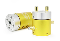
Every seal selection involves a delicate balance between performance, longevity, and cost. The materials you choose—whether PTFE, elastomers, or engineered thermoplastics—each come with inherent compromises. For instance, higher chemical resistance often means sacrificing flexibility or low-temperature performance. Ignoring these trade-offs can lead to premature failure, unexpected downtime, or safety risks that far outweigh the initial savings.
Another critical consideration is the sealing mechanism itself. Dynamic seals designed for rotating shafts may struggle in high-speed applications if the contact pressure is not precisely managed, leading to excessive heat buildup and wear. On the other hand, static seals face challenges like creep relaxation under sustained pressure, demanding careful material selection and groove design. Understanding the specific demands of your application is the only way to navigate these compromises effectively.
Finally, the operating environment plays a huge role in dictating which trade-offs are acceptable. Temperature swings, abrasive media, or pressure spikes can rapidly degrade seals that performed perfectly in controlled lab tests. Real-world conditions often force you to prioritize certain properties over others—perhaps choosing a harder compound that resists extrusion but increases friction, or opting for a more expensive material to avoid frequent replacements in hard-to-access locations. Making informed choices here separates a reliable system from a costly liability.
The Hidden Impact of Fluid Dynamics on Joint Efficiency
Synovial fluid isn’t merely a passive lubricant; it exhibits complex non‑Newtonian behavior that dynamically adapts to shear rates. During rapid movements, its viscosity drops to minimize friction, while under sustained pressure it thickens to cushion cartilage surfaces. This rheological duality ensures that joints operate with minimal energy loss, yet the sheer thinness of the fluid film—often less than 50 micrometers—leaves little margin for error. Even subtle changes in fluid composition or pressure distribution can shift the system from near‑frictionless gliding to abrasive contact, quietly undermining joint integrity over time.
Beyond lubrication, the fluid acts as a metabolic lifeline. Cartilage, being avascular, relies entirely on convective solute transport driven by joint motion. With each compression cycle, fluid exudes from the matrix, carrying waste products, while re‑expansion pulls in fresh nutrients like glucose and oxygen. This convective turnover is exquisitely sensitive to flow patterns; stagnant zones can starve chondrocytes and trigger catabolic cascades long before structural damage becomes radiographically visible. The hidden efficiency of a joint, then, is not just mechanical—it’s a delicate thermodynamic balance maintained by micro‑scale fluid currents.
Perhaps the most overlooked consequence is the role of fluid dynamics in proprioceptive feedback. Intra‑articular pressure fluctuations and fluid shear activate mechanoreceptors that fine‑tune muscle co‑activation and joint stability. When fluid film breakdown occurs—whether from aging, injury, or inflammation—these signals distort, leaving the joint vulnerable to eccentric loading and micro‑trauma. In this sense, fluid dynamics isn’t merely a passive contributor; it’s a regulatory loop that governs long‑term resilience. Disrupting it doesn’t just increase friction—it erases a critical layer of neuromuscular control, setting the stage for accelerated degeneration.
Precision Machining Standards That Separate Good from Great
In precision machining, hitting the nominal dimension isn’t enough. True excellence lies in understanding the part’s functional intent—how it mates, where it wears, and which features carry load. Shops that consistently deliver greatness study the assembly context, not just the print. They might slightly tweak a surface finish beyond spec to reduce friction in a sliding pair, or hold a bore tolerance tighter than required because they know it houses a press-fit bearing. This anticipatory engineering, born from dialogue with designers and deep manufacturing experience, transforms a compliant part into a component that elevates the entire product.
Process control extends far beyond CMM reports. Great shops treat every operation as a closed-loop system, capturing real-time data on tool wear, thermal drift, and coolant chemistry. Instead of waiting for a non-conformance, they correlate spindle load spikes with impending edge failure and swap inserts before a single feature drifts. Their inspection strategy isn’t about lot acceptance; it’s about process learning. Measurements at specific intervals feed back into the CAM model to automatically offset tool paths, keeping the process centered over thousands of cycles. This obsession with micro-adjustments keeps process capability indices above 1.67 while competitors struggle to maintain 1.33.
Then there’s the discipline of surface integrity. While most shops chase Ra numbers, the great ones consider subsurface damage, residual stress patterns, and white layer formation after grinding or EDM. They might slow down a finishing pass to avoid tensile stresses that lead to fatigue cracking, or specify cryogenic cooling for titanium to prevent alpha-case formation. Such nuance often goes unnoticed in first-article inspection, but it separates parts that barely pass a fatigue test from those that survive decades in service. This layer of craftsmanship is what earns a machine shop long-term partnerships on mission-critical components.
Thermal Management Tricks the Datasheets Won’t Tell You
Most datasheets focus on ideal lab conditions, but real-world thermal performance often hinges on the mundane details they skip. For instance, the thermal resistance numbers given for a heatsink usually assume a perfectly flat, polished surface mating with the component. In practice, even tiny air gaps from slight warping or surface roughness can cripple heat transfer. A trick veterans learn is to intentionally use a slightly thicker layer of thermal paste than recommended—counterintuitively, the extra paste can fill microscopic valleys on uneven surfaces, drastically lowering junction temperatures when mounting pressure is uneven. It's a messy solution, but it works when precision machining isn't an option.
Another unspoken variable is the role of the PCB itself as a heat spreader. Datasheets list thermal pad dimensions, but they rarely mention that pouring copper pours on inner layers directly under hot components can pull heat away far better than any top-side heatsink alone. Designers often overlook that the dielectric material between copper layers acts as a significant thermal barrier, so placing thermal vias under a part without connecting them to a solid internal plane is nearly useless. The real art is in stitching multiple small vias tightly around the pad edges, filled with solder to reduce air pockets—something you'll never find in a typical application note.
Then there's the issue of transient thermal response that datasheets obscure with a single “thermal time constant.” In bursty applications, like motor controllers or RF amps, the peak temperature can spike far beyond the steady-state prediction if you rely solely on bulk heatsink capacity. A cheap fix is to bond a small copper coin directly to the component case with thermally conductive epoxy before attaching the main heatsink; the coin acts as a fast-response heat reservoir, smoothing out those millisecond-level surges. This bodged-on thermal capacitance can prevent instantaneous thermal runaway scenarios that would otherwise force you to derate a part by half its rated power.
Real-World Testing Protocols Beyond Standard Certifications
While standard certifications validate baseline performance under controlled lab conditions, they rarely capture the erratic behavior of real-world power grids. Voltage sags, frequency fluctuations, and harmonics introduce complexities that certification tests—often conducted with ideal sinusoidal inputs—simply overlook. To bridge this gap, rigorous in-situ testing is essential, exposing inverters and power converters to the messy, unpredictable electrical environments they’ll actually face. This means moving beyond the climate chambers and calibrated loads of the lab, and into environments where grid impedance varies, loads switch abruptly, and thermal conditions shift without warning.
Field testing should reproduce the worst-case scenarios: rapid cloud transients that cause solar inverters to repeatedly connect and disconnect, unbalanced grid phases that stress three-phase equipment, and voltage ride-through events where the equipment must stay operational during brief but severe dips. Testing protocols must also account for cumulative wear—repeated cycling of relays, capacitors degrading under high ripple currents, and firmware glitches triggered by rare grid anomalies. By logging high-resolution data over months, not hours, we uncover failure modes that accelerated life testing misses, like corrosion accelerated by humidity combined with electrical stress, or software hangs induced by specific sequences of grid events.
Equally important is interoperability testing within the ecosystem of devices that share the same point of common coupling. No inverter operates in isolation: interactions with neighboring PV systems, battery storage, and even electric vehicle chargers can trigger protective shutdowns or resonance issues that individual certifications ignore. A robust protocol includes diverse load and generation mixes, intentional islanding tests, and communication protocol stress tests to ensure seamless integration. Ultimately, the goal is to design a validation framework that treats the grid not as a fixed backdrop, but as a dynamic, sometimes hostile participant, ensuring reliability where it matters most—in the field.
FAQ
Look beyond just the price tag. A manufacturer's engineering expertise, material traceability, and track record in your specific industry often reveal far more. Check whether they invest in in-house testing rigs that simulate real operating conditions—pressure spikes, temperature extremes, continuous run cycles. Access to post-sale support, like on-site troubleshooting or custom retrofit guidance, also separates a transactional supplier from a true partner.
Materials directly dictate how a joint handles corrosion, thermal expansion, and wear. For instance, stainless steel bodies resist chemical attack in food processing, while duplex alloys hold up better in marine environments. But it’s not just the housing—carbon graphite seals paired with ceramic faces can dramatically reduce friction in dry-running scenarios. Mismatching materials to the media or temperature range leads to micro-cracks, pitting, and early seal failure.
Seals are the first line of defense, but their performance hinges on the design around them. Spring-energized PTFE seals cope with aggressive chemicals, while multi-lip elastomer designs handle thermal cycling better. Balanced mechanical seals with proper surface finishes on the mating rings prevent fluid from escaping even when pressure fluctuates. The real trick is compensating for axial and radial shaft movements without binding—poorly specified seals here lead to slow drips that suddenly escalate.
Friction heat builds fast at high speeds, degrading lubricants and softening seal materials. Without heat-dissipating features like jacketed housings or integrated cooling channels, a joint can warp enough to misalign the internal components. Thermal expansion differences between shaft and housing also need accounting—otherwise you get galling. In some cases, simply upgrading to a rotary union with a floating rotor can maintain concentricity as temperatures climb.
Standard joints often force compromises in piping layout or machine geometry. A tailored design can incorporate multiple passages within a compact envelope, offset porting to dodge obstacles, or integrate sensors for real-time monitoring. It also lets you match bearing arrangements to unusual load patterns—like cantilevered moments in robotic arms. The upfront engineering time typically pays off through fewer adapters, reduced leak points, and simpler installation.
Consistency in a few simple steps makes the biggest difference. Regularly flush the joint when switching between incompatible fluids to prevent residue buildup that scores sealing faces. Monitor drain lines, not just inlet pressure—a clogged drain often signals an impending seal failure. Torque checks on mounting bolts prevent gasket crush issues. And storing spare joints in climate-controlled conditions avoids elastomer hardening before they're even installed.
You want a factory that test runs every joint under conditions slightly beyond its rated specs—not just one sample per batch. Hydrostatic tests at 1.5 times working pressure, helium leak detection for gas applications, and spin tests at maximum RPM with temperature cycles weed out latent flaws. The best manufacturers also record actuation torque breakaway values on assembled units, which predicts early-life performance hiccups.
Subtle clues often appear before a catastrophic leak. A sudden increase in drive motor current can indicate higher torque resistance from a failing bearing. Intermittent pressure drops in the supply line may point to an internal seal bypass. Visual signs like steam moisture around a joint on dryer rollers or uneven wear patterns on slip rings shouldn't be ignored. Vibration analysis trending upward is another reliable early warning.
Conclusion
Achieving optimal performance in rotary joints demands a holistic approach that begins with material selection. The alloys and composites chosen directly govern longevity, as mismatched materials can lead to premature wear under thermal and mechanical stress. Factories excelling in this domain pair robust metallurgy with precision machining, ensuring that every surface finish and tolerance contributes to seamless rotation. This eliminates micro-leaks and friction hotspots, setting apart truly great joints from merely adequate ones. Beyond the solid components, seal technology introduces critical trade-offs: aggressive sealing may increase drag, while looser fits risk leakage. Smart factories balance this by leveraging computational fluid dynamics to map internal flows, turning a hidden efficiency drain into a design advantage. They don’t just follow datasheets; they manipulate coolant pathways and thermal expansion coefficients to maintain stability under fluctuating loads.
Thermal management, often glossed over in product specs, becomes a cornerstone of reliability when addressed creatively—using advanced coatings or integrated heat sinks that dissipate energy without adding bulk. Yet, real confidence comes from testing protocols that go beyond standard certifications. Leading manufacturers subject their joints to prolonged cyclic loads, pressure spikes, and medium variations that mimic actual operating extremes. These real-world simulations expose weak points invisible in conventional lab tests, inspiring iterative refinements in both design and assembly. Ultimately, the factory’s insight lies in synthesizing these elements: marrying material science, seal dynamics, fluid behavior, machining artistry, thermal cunning, and brutal honesty in testing to deliver rotary joints that sustain peak performance year after year.
Contact Us
Contact Person: Xiangpin Li
Email: [email protected]
Tel/WhatsApp: 86 186 1706 8578
Website: https://www.moflon.com